Table of Contents
Using TagConnect adapter for SWD interface
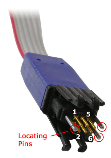
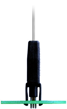
Some years ago in 8-bit times when I was AVR fan, I have been aware sleek, low-footprint TagConnect Pogo pin interface for Programming and Debuging the MCUs, initially Microchip's PIC series, which made me a bit jealous and highly motivated me in buying them. It has two footprints: legged and no-legs (-NL suffix). The bigger one has hooks for holding in place, which is for comfortable debugging.
The smaller footprint is great for fast in-system programming on your final product's assembly line. It is inly about 1 cm^2 large.
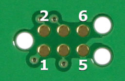
This is the footprint for its corresponding ICD cable-to-board connector:
As folks around know, I prefer Segger's J-Link over STLink, because it supports virtually unlimited breakpoints and is much faster overall, so I bought one and never looked back. That was the reaason I decided to push a bit further and create my own TagConnect J-Link adapter.

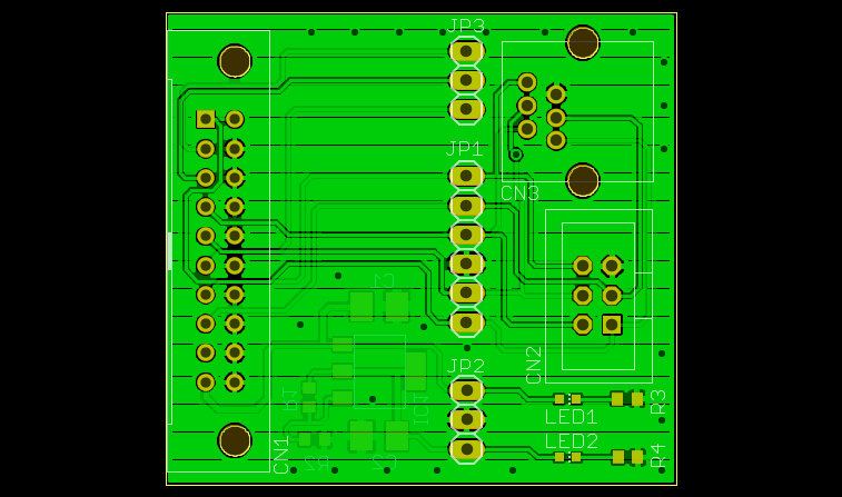
As you can see, the board contains selectable 1117-style 3.3V/0.3A LDO, as well as all JTAG pins placed conveniently on a header, which may be nice to have. Heck, you can even ignore the TagConnect and use the board as a PSU + debug interface.
Powering the target board externally
The board has now external power. To enable the power permanently, follow this procedure (probably Windows only):
- Connect J-Link to the PC via USB
- Start J-Link Commander (JLink.exe)
- Enter the “power on perm” command without quotes to enable target power by default.
Board available for sale
Revision 4 board is available now. It has resistor-programmable LDO (pre-programmed for 3.3 V operation) for external power, RJ12 and IDC sockets. You can buy it at my Tindie store.


